Abstract
American Society of Mechanical Engineers B31.5 Refrigeration Piping and Heat Transfer Components (B31.5) has been an independent Section of the ASME B31 piping codes since 1962 and is cited in prominent refrigeration industry documents such as ANSI/ASHRAE Standard 15 (American Society of Heating, Refrigerating and Air-Conditioning Engineers), ANSI/IIAR 2 (International Institute of Ammonia Refrigeration) and the IMC (International Mechanical Code). It’s relatively short at just over 100 pages, given that its companion codes in the power plant and process industries are nearly three and six times as long, respectively. Yet it remains largely unknown to many in the industrial refrigeration business outside of liquid refrigerant piping schedule and carbon steel MDMT requirements. A common misconception of B31.5 is that refrigerant piping stress analysis is not required, when nearly the exact opposite is the case and has been so for nearly 60 years. OSHA PSM regulation of most ammonia refrigeration systems and increasing use of CO2 refrigerant operating at pressures of 580-1,885 psig (40-130 bar) add to the importance of understanding this language correctly.
Refrigeration system designers and users incur regulatory liability from their design documents’ claims of B31.5 compliance when these are based on only partial knowledge of its requirements. This article will clarify these requirements, suggest current and legacy resources for accomplishing the calculations and hopefully promote a greater overall familiarity with B31.5.
History
ASME was founded in 1880 in response to a rising number of steam boiler explosions. The well-known Boiler and Pressure Vessel Code (B&PVC) was first published in 1914 and the National Board of Boiler and Pressure Vessel Inspectors was formed in 1919 to provide uniform interpretations of the B&PVC. In 1926, ASME requested the American Engineering Standards Committee (forerunner of today’s American National Standards Institute, ANSI) to develop the B31.1 American Tentative Standard Code for Pressure Piping, first published in 1935. This document contained chapters on piping specialties such as power, process, refrigeration, gas transmission, etc., which the ASME B31 Committee began separating into 13 independent Sections in 1955.
The first edition of B31.5 (formerly chapter 5) was published in 1962. Substantial portions of this publication’s text can be found with little or no change in the current 2019 version. In particular, its scope has remained consistent and is currently defined as:
- 500.1 This Code prescribes requirements for the materials, design, fabrication, assembly, erection, test, and inspection of refrigerant, heat transfer components, and secondary coolant piping for temperatures as low as -320°F (-196°C), whether erected on the premises or factory assembled, except as specifically excluded in the following paragraphs.
- 500.1.1 This Code shall not apply to any of the following:
- (a) any self-contained or unit system subject to the requirements of Underwriters Laboratories or other nationally recognized testing laboratory.
The current Code introduction contains two statements that also have been in effect for decades and are of importance to the end user. The first of these seems simple enough in that it selects the appropriate Code Section (power, process, transmission, refrigeration, etc.) for the piping system, but it immediately establishes the owner’s engagement and obligation. The second reinforces a comprehensive application of the Code wherever it applies.
It is the Owner’s responsibility to determine which Code Section is applicable to the piping installation.
All of the applicable requirements of the selected Code Section must be followed.
Allowable stress is of primary importance to all ASME piping Code sections and is mentioned over 70 times in B31.5. Maximum allowable stress values (MASV) are given for specific pipe materials and cannot normally be exceeded by any sustained combination of stresses resulting from effects of pressure, temperature, live or dead loads, external forces such as wind, seismic and vibration as well as thrusts and moments resulting from piping system expansion and contraction. Brief excursions above MASV due to system pressure and/or temperature variations are allowed.
Refrigeration resources refer to B31.5 as follows:
- ANSI/ASHRAE Standard 15
- 1971-1992 §8.4.1
- 1994-2013 §9.10.1 and various normative appendices
- 2016-current §9.10.1 and Normative Appendix B
- ANSI/IIAR 2
- 1974 §5.2.1
- 1984 and 1992 §3.12 and §5.2.1
- 1999 §7.1.1
- 2008B §10.1
- 2014 (current) §13.1
- BSR/IIAR CO2 -201x §9.2.2 (currently in draft)
- IMC
CODE ANALYSIS
B31.5-2016 is organized into six chapters, of which Chapter II (Design) will be discussed here. To highlight the Code basis for piping stress analysis, the appropriate parts of Chapter II are listed by paragraph number with a brief discussion of their topics and followed by a more complete examination of §519.4.1 - §519.4.4. B31.5 uses the terms “section” and “paragraph” interchangeably in the text; the capitalized term “Section” refers to a Section of the B31 code family.
Chapter II – Part 1 (Conditions and Criteria, §501-§502)
- §501 Design Conditions
- §501.2 Pressure – internal and external pressure requirements.
- §501.3 Temperature – defines metal temperature and warns designer of low temperature brittle fracture situations.
- §501.5 Dynamic Effects – effects of impact, wind, earthquake, vibration, etc.
- §501.6 Weight Effects – live (fluid, snow and ice) and dead (pipe, valves and insulation) loads.
- §501.7 Thermal Expansion and Contraction Loads – first mention of stress from restraint of thermal expansion and contraction.
- §502 Design Criteria
- §502.2.3 Variations From Normal Operation – allowance for limited magnitude and duration of excessive pressure and temperature.
- §502.2.6 Use of Criteria – linkage of pipe wall thickness to design conditions and first mention of allowable material stresses.
- §502.3 Allowable Stresses and Other Stress Limits
- §502.3.1 Allowable Stress Values
- (a) Defines Table 502.3.1 to show allowable stress values for piping design.
- (b) Defines allowable stress design basis for ferrous material.
- (c) Defines allowable stress design basis for nonferrous material.
Chapter II – Part 2 (Design of Piping Components, §503-§504)
- §504 Pressure Design of Piping Components
- §504.1 Straight Pipe
- §504.1.1 General – provides the basic formula (2) for pipe wall thickness which includes the pressure design basis, mechanical allowances (thread depth, groove depth and wall thickness tolerance) and material allowances for corrosion and erosion.
- §504.1.2 Straight Pipe Under Internal Pressure – provides formulae (3a) or (3b) for internal pressure design wall thickness of pipe with Do/t > 4(outside diameter/wall thickness > 4). This applies to carbon steel (CS) pipe sizes ½”-36” and schedules 10-XXS except for ½”-¾”-1” in XXS.
Chapter II – Part 3 (Design Application of Piping Components Selection and Limitations, §505-§508)
- §505.1 General – mandates that pipe meeting the standards and specifications listed in Table 502.3.1 shall be used within temperature and stress levels defined in §502.3.1 and Table 502.3.1.
- §505.1.1 – sets minimum wall thickness for various combinations of refrigerant phase, refrigerant group and nominal pipe size.
- §505.2.1 Nonferrous Pipe or Tube – allows various pipe materials in refrigerant service given refrigerant-material compatibility and compliance with §504.1 and allowable stress values in Table 502.3.1.
Chapter II – Part 4 (Selection and Limitations of Piping Joints, §510-§518)
- §517(f) – requires that piping using brazed joints shall be designed with allowance for base material strength reduced to annealed levels.
Chapter II – Part 5 (Expansion, Flexibility, Structural Attachments, Supports, and Restraints, §519-§521)
- §519.4.1 Calculations/Tests – states that “Formal calculations or model tests shall be required only where reasonable doubt exists as to the adequate flexibility of a system.”
- §519.4.2 Flexibility – defines the basis for assumption of adequate flexibility in parts (a), (b) and (c).
- §519.4.3 Methods of Analysis – defines the analytical method selection criteria for piping systems that do not meet the requirements of §519.4.2.
- §519.4.4 Standard Assumptions – requires that a piping system between anchor points be treated as a whole, including the effects of restraints, support friction and movement of equipment to which the piping system is attached.
The critical paragraphs of B31.5 concerning pipe stress analysis are §519.4.1, §519.4.2, §519.4.3 and §519.4.4, each of which will be analyzed below. The language in these paragraphs is virtually unchanged since the 1962 edition of the Code, which preserves a less definite writing style now avoided in such documents. The current preference is for normative language which defines types and values of physical parameters, indicates actions to be taken in response to these parameters, minimizes subjective interpretation and avoids exceptions to the requirements.
The phrase “piping system” is used throughout the Code and is defined here to be a piping network operating within a band of temperature and/or pressure such that a change in either of these parameters affects the entire network. Examples include the LTRL, LTRS, HTRL, HTRS, HGD, HPL and other well-defined portions of the refrigeration system.
As mentioned earlier in a brief description of §501.7, many pipe stresses result from temperature-induced contraction and/or expansion of the piping system. These depend on differences between minimum and/or maximum operating temperatures and the piping network temperature at the time of construction. Table 519.3.1 lists thermal expansion in units of inches/100 feet (mm/m) with an assumed construction temperature of +70°F (+21°C). Carbon steel’s thermal expansion range of 0.007”/100’/°F (0.0104mm/m/°C) is approximately ⅔ that of stainless steel or copper. A sample calculation for 300’ (91.4m) of CS piping installed at +70°F (21°C) and operated at -40°F (-40°C) shows an overall shrinkage of 2.31” (58.7mm).
§519.4.1 Calculations and Tests
Formal calculations or model tests shall be required only where reasonable doubt exists as to the adequate flexibility of a system.
The phrase “reasonable doubt” allows for precisely the opposite of the normative language style mentioned above. Interpretations of this phrase vary so widely that it becomes difficult to determine the Code’s direction and the term “adequate flexibility” provides little more in the way of definition, although this improves in the next section. These uncertainties have led many to conclude that §519.4.1 is sufficiently indefinite that neither further Code examination nor piping stress analysis is required. As will be shown in discussion of the next two sections, this is not the case.
§519.4.2 Flexibility
Adequate flexibility may generally be assumed to be available in systems that
(a) are duplicates of successfully operating installations or replacements of systems with a satisfactory service record
(b) can be readily adjudged adequate by comparison with previously analyzed systems
(c) are of uniform size, have no more than two points of fixation and no intermediate restraints, are designed for essentially noncyclic service (less than 7,000 total cycles), and satisfy the following approximate criterion:
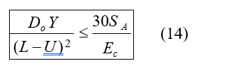
Do = outside diameter of pipe, in. (mm)
Ec = modulus of elasticity of the piping material in the cold condition, ksi (MPa)
L = developed length of piping between anchors, ft (m)
SA = allowable stress range from eq (1) ksi (MPa), include stress range reduction factor, f, where more than 7,000 cycles of movement are anticipated during the life of the installation (see Fig. 502.3.2)
U = anchor distance (length of straight line joining anchors), ft (m)
Y = resultant of movements to be absorbed by pipeline, in. (mm)
§519.4.2 substantially clarifies the Code’s intent even though non-normative language still exists throughout the paragraph. Parts (a), (b) and (c) describe piping system conditions, all of which must be met to satisfy the general assumption of adequate flexibility and thus avoid stress analysis.
Part (a) includes two conditions, each of which involves system replication and each of which contains non-normative language. The word “duplicates” requires that the piping system be an exact copy of the original design, a situation seldom found in new construction. The second condition allows for somewhat more latitude by use of the term “replacements” without specifying how faithfully the original design has been replicated. Each phrase includes informative language such as “successfully operating” and “satisfactory service record”. Since there is no way to quantify these concepts beyond avoidance of outright piping failure, this paragraph only begins to explain the Code’s ultimate direction.
Part (b) carries this effort further by means of two phrases, the first of which appears initially vague due to the words “readily adjudged adequate”. The second expression “previously analyzed systems” solidifies this part’s definition by requiring enough systems to have been stress analyzed to demonstrate sufficient adequacy of judgment in comparison with new designs.
Part (c) consists of four requirements: the piping system must be of “uniform size”, have no more than two anchor points and be without intermediate restraints, undergo less than approximately 7,000 cycles in its lifetime and satisfy a criterion meant to maintain terminal reactions below a given level.
- Piping systems of uniform size are rare in all but the smallest self-contained equipment refrigeration design.
- Restriction to no more than two points of fixation provides for a piping system that is not over-constrained and thus subject to unnecessary stresses. A LTRS system, for example, is frequently anchored in the machinery room at the recirculator vessel nozzle connection and in the plant at the evaporator suction line connection. Any other anchor restricting the piping system’s movement violates this requirement. In addition, friction between any piping system and its supports can become a restraint and is specifically mentioned in §519.4.4.
- A process freezing LTRS network with pipe temperatures cycling daily due to freezing and cleanup operation while operating six days a week and 50 weeks a year would take approximately 23.3 years to accomplish 7,000 cycles. This is likely to coincide approximately with equipment replacement and thus likely to be a condition that satisfies §519.4.2.
- This criterion comes with substantial controversy over its use. The B31.5-1962 edition included language stating “compliance with this formula does not assure that terminal reactions will be satisfactory”, but all such warnings had been removed in the 1983 and later versions. By contrast, ASME B31.1 Power Piping and ASME B31.3 Process Piping are used all over the world and each of them retains similar language in their 2012 and 2016 editions, respectively. Leaving these differences aside, review of this condition’s terms quickly shows that the Y variable requires finding the resultant of the movements to be absorbed by the pipeline in inches (mm) and this cannot be done without some level of pipe stress calculation.
In summary, §519.4.2 contains six conditions with which a piping system must comply in order to assume adequate flexibility is available without analysis. For new construction of industrial refrigeration piping, parts (a) and (c-1) cannot be satisfied by definition. Part (b) requires that the number of previously analyzed systems be sufficient to prove judgment capable of determining suitable flexibility merely by comparison and thus raises the question of why those previous levels of engineering analysis would not be applied to a current system. Part (c-2) requires proof that no intermediate restraints or supports restrict piping system expansion or contraction and this would be difficult to prove without analysis. Part (c-4) is defined as applicable in B31.5-2016, but has historical and current cautions against its use in multiple Sections of the B31 family of codes. Only part (c-3) appears to offer a reasonable chance of compliance from the system.
519.4.3 Methods of Analysis
Systems that do not meet the requirements of para. 519.4.2 shall be analyzed by a method appropriate to the hazard entailed by failure of the line, the importance of maintaining continuous service, the complexity of the layout, and strain sensitivity of the pipe material.
§519.4.3 reinforces the requirement for stress analysis by referring to “the requirements” collectively. There is no allowance for partial compliance with §519.4.2.
The four conditions governing level of analysis point to a thorough solution. The relatively high pressures of CO2 and hazardous material status of NH3, combined with the production consequences of loss of service, support a rigorous level of analysis. Refrigerant piping layouts are seldom simple. Finally, strain sensitivity of the piping material, particularly if CS piping operating temperatures are lowered beyond MDMT after startup, is a continuing problem. These concerns support simple analyses only if they provide demonstrably compliant designs that include descriptions of the analytical method and any assumptions.
§519.4.4 Standard Assumptions
Standard assumptions specified in para. 519.3 shall be followed in all cases. In calculating the flexibility of a piping system between anchor points, the system shall be treated as a whole. The significance of all parts of the line and of all restraints…solid hangers and guides…intermediate restraints…restraint introduced by support friction, shall be recognized.
§519.4.4 summarizes the stress analysis design basis by emphasizing that the system must be treated as a whole between anchor points, particularly when smaller branch lines are subject to movements by larger and/or longer pipe mains. Listing of the restraints insures that those few systems which can be simply analyzed include all such factors, while computerized analyses of more complex arrangements will require that they be drawn in by definition. In addition, friction at piping supports and movement of equipment to which the piping may be attached are two conditions less commonly included.
CONCLUSION
The basic direction of any Section in the B31 Code family is to insure that piping systems are designed, constructed and operated within temperature and stress limits of suitable pipe material fabricated in appropriate wall thicknesses. §502.2.6, §502.3.1(a) and §505.1 are the regulatory bases for these statements in B31.5 and they lead directly to the requirements for stress analysis found in §519.4.1-§519.4.4.
A complete reading of these four sections removes much of the confusion over applicability of piping stress analysis. Those few systems which legitimately do not require such calculations are well defined and the remaining majority of piping systems have an understandable design basis in other sections of B31.5. Failure to complete this analysis through neglect, benign or otherwise, leaves the designer and end user with an incomplete picture of their system, little in the way of defense against citation and, at any moment, facing the old saying about taxes: to avoid is legal – to evade is not. Hopefully, the information presented here, when combined with further efforts in education and training, will reduce such occasions to a minimum.
RESOURCES
The early 1970s saw the first use of mainframe computers for stress calculation and software is now available from multiple vendors for purchase or rental using desktop computers. However, for those interested in the background and methods used before computers, two books listed in the Bibliography will be helpful: Piping Design and Engineering by Grinnell (Grinnell, 1963; out of print but available by search) and Design of Piping Systems by M. W. Kellogg (Wiley & Sons, 1956; reprinted by Martino, 2009). Each of these books has detailed descriptions of stress analysis techniques. Although most engineers will choose to use software, the hand approaches allow quick calculations of simple systems and can provide reality checks for computer solutions.
IIAR has published two important papers on this subject: Pipe Stress or Flexibility Analysis in Refrigeration Piping (Riley, 2000) and The Economics of Computer Modeled Central Ammonia Systems vs. the Use of Impact Tested Pipe and Fittings (Golden and McNally, 2008). Riley gives an excellent overall description of the stress analysis process and mentions that the Grinnell book has “compiled tables of precalculated shapes to allow quick determination of forces and moments” for the reasons mentioned above. Golden and McNally describe stress analysis requirements as part of a larger discussion of reducing piping system stress to allow use of non-impact tested material for CS piping systems below -20°F. Although outside the scope of this paper, this approach bears reading due to the reduction in piping cost and lead time possible from use of more commonly available material.
Finally, ASME has two additional resources which may be useful. The first is ASME B31G Manual for Determining the Remaining Strength of Corroded Pipelines. As mentioned above, minimum pipe wall thickness is determined by calculations involving pressure, pipe parameters, allowable stress and corrosion allowance. Dividing actual thickness by minimum thickness produces the safety factor (SF), which decreases when actual thickness is reduced by corrosion. B31G suggests values for SF which will assist the user in deciding whether that portion of the system needs replacement. The second is a two-day ASME Masterclass Bases and Application of Piping Flexibility Analysis to ASME B31 Codes, given at various locations and times across the USA. The class is geared to the experienced engineer/designer and taught by senior B31 Committee personnel to show design approaches for conditions of pressure, temperature and pipe size substantially beyond those of refrigeration applications.
BIBLIOGRAPHY
- Refrigeration Piping, ASA B31.5-1962, American Society of Mechanical Engineers, 1962.
- Refrigeration Piping, ANSI/ASME B31.5-1983, American Society of Mechanical Engineers, 1983.
- Refrigeration Piping and Heat Transfer Components, ASME B31.5-2016, American Society of Mechanical Engineers, 2016.
- Safety Code for Mechanical Refrigeration, ASHRAE Standard 15-70, American Society of Heating, Refrigerating and Air-Conditioning Engineers, Inc., 1971.
- Safety Code for Mechanical Refrigeration, ANSI/ASHRAE 15-1994, American Society of Heating, Refrigerating and Air-Conditioning Engineers, Inc., 1994.
- Safety Standard for Refrigeration Systems, ANSI/ASHRAE Standard 15-2016, American Society of Heating, Refrigerating and Air-Conditioning Engineers, Inc., 2016.
- Equipment, Design, and Installation of Ammonia Mechanical Refrigeration Systems, ANSI/IIAR 74-2, International Institute of Ammonia Refrigeration, 1974.
- Equipment, Design, and Installation of Ammonia Mechanical Refrigeration Systems, ANSI/IIAR 84-2, International Institute of Ammonia Refrigeration, 1984.
- Safe Design of Closed-Circuit Ammonia Refrigeration Systems, ANSI/IIAR 2-2014, International Institute of Ammonia Refrigeration, 2014.
- 2018 International Mechanical Code, International Code Council, 2017.
- Piping Design and Engineering, second edition, Grinnell Company, Inc., 1963.
- Design of Piping Systems, The M. W. Kellogg Company, Martino Publishing, 2009.
- Pipe Stress or Flexibility Analysis in Refrigeration Piping, Riley, International Institute of Ammonia Refrigeration, 2000.
- The Economics of Computer Modeled Central Ammonia Systems vs. the Use of Impact Tested Pipe and Fittings, Golden and McNally, International Institute of Ammonia Refrigeration, 2008.
- Bases and Application of Piping Flexibility Analysis to ASME B31 Codes, MC110, ASME, 2018.
James Caylor, PE, is an independent consulting Mechanical Engineer specializing in NH3 and CO2 Refrigeration Systems used in process and cold storage applications. Clients have included Leprino Foods, Safeway, Dreyer’s, Tyson, ConAgra, Unilever, Nestlé, Imperial Irrigation District, Lineage Logistics, and Grupo Kuo (Kekén). Mr. Caylor has also consulted for lawyers representing a food processing firm facing EPA citations at multiple plants. His forensic analysis services are available to attorneys representing plaintiff and defendant and include site review, thorough reporting, depositions, and trial testimony as needed.
©Copyright - All Rights Reserved
DO NOT REPRODUCE WITHOUT WRITTEN PERMISSION BY AUTHOR.